Projects Machine Vision 3d Engine Block Inspection
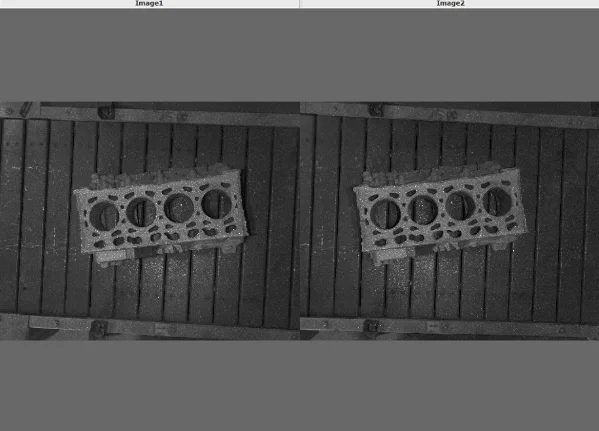
Unprocessed Images with Random Pattern Projection
Engine blocks make a good subject for machine vision as they are so feature-rich with plenty of geometric patterns. When a freshly casted and machined engine block is born, it has to be inspected by eye to ensure both that it is complete and that the dimensions of the visible features meet the specification requirements. Traditionally, a time consuming and labour-intensive task that has required manual measurements using callipers and micrometers.
An additional problem is presented by the volume of engine blocks that are produced in some factories – a recent statistic in 2018 showed that 60% of the worlds engine blocks are produced in China and many of these from just a handful of factories. So the volume of production also dictates that not every engine block can be manually inspected, therefore the inspection is limited to a certain percentage of the production.
Automation of feature measurements using robotics is, of course, the way forward and there are a number of systems that inspect and measure using two dimensional vision systems.
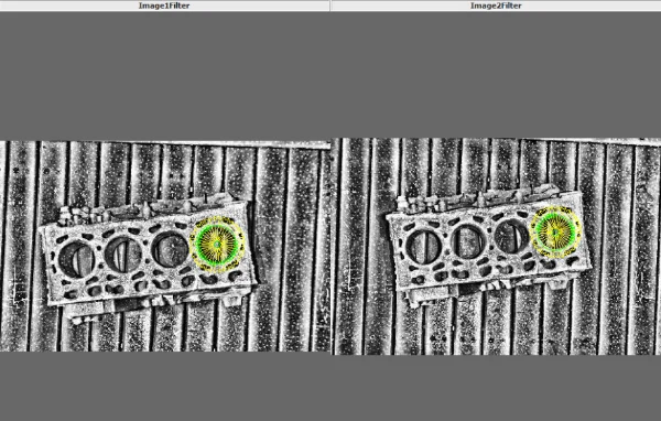
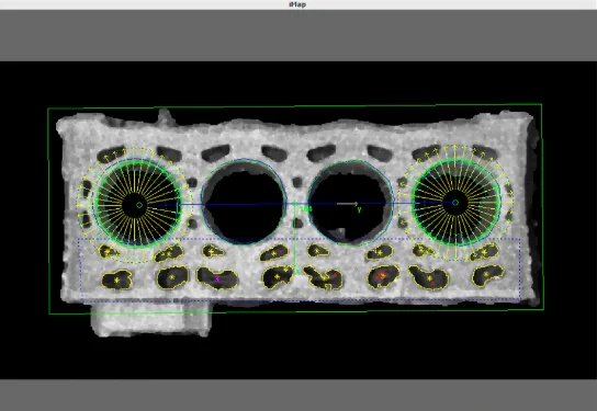
Scorpion Vision has supplied a number of engine block inspection systems that use a combination of 2D and 3D stereo vision cameras to measure engine block features. The 3D functionality enables non-contact measurement of the engine blocks as image distortion caused by perspective is corrected using 3D calibration – 2D images are re-sampled using data derived from the 3D algorithms, removing perspective and therefore correcting the 2D measurements.
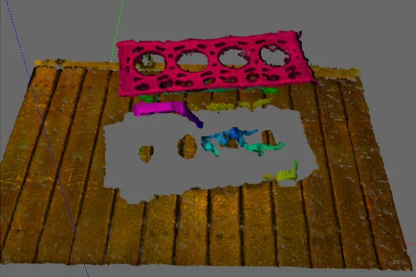
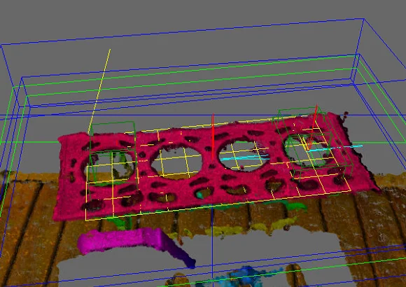
The 3D Point Cloud is Generated from the raw images. The plane of the top of the engine is found to get the spatial orientation
The same point is found in both images and with a series of stereoscopy tools and reference changes the 3D pose is calculated.
GET IN TOUCH
We are always delighted to hear from our customers. If you’d like to ask a question, make an enquiry or request support, please contact us through one of the methods below or by using the enquiry form.
Telephone: +44 (0) 1590 679333
Sales: [email protected]
Technical: [email protected]